Solenoid engines are an interesting concept, they are most likely one of the most inefficient ways to turn electricity into rotary motion. And while high speeds are possible the torque is generally very low. But that is not the point of a solenoid engine. They give the feeling of old technology and steam powered generators and that makes them so interesting to watch.
A couple of weeks ago I made a solenoid engine using only one solenoid. I had a blast making it and the result is very cool and satisfying to look at. I learned a lot from this first build so now it’s time to take it a step further and build a four stroke version.
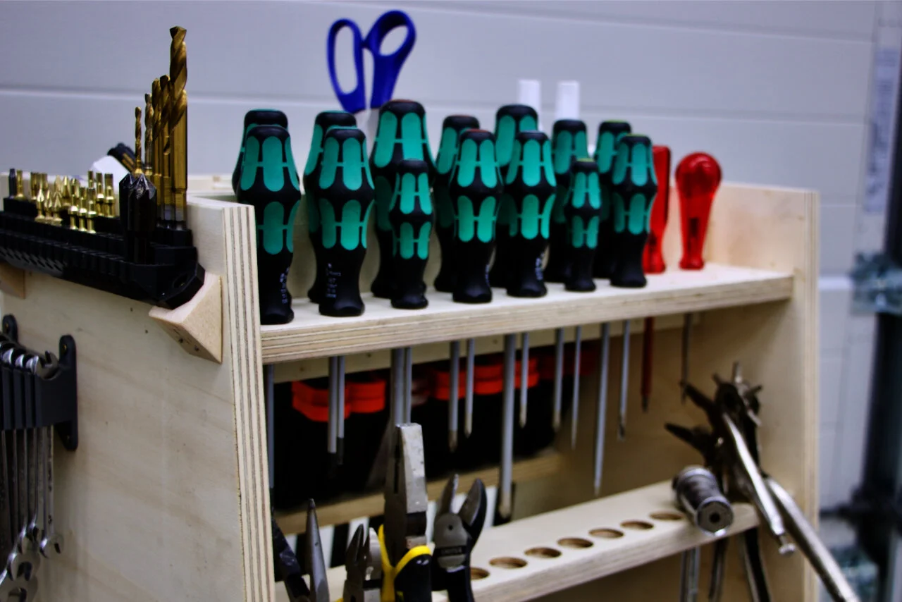
What I used to make it:
(Vintage) Lathe
Drillpress
Router (table)
Bandsaw
Disk sander
Cordless drill
3D Printer
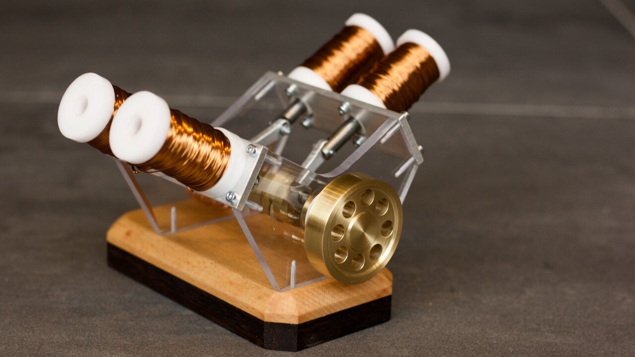
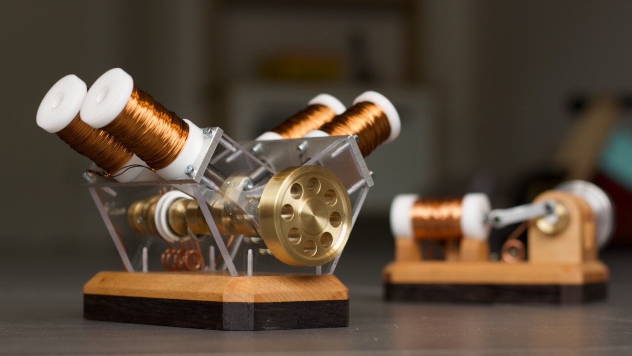
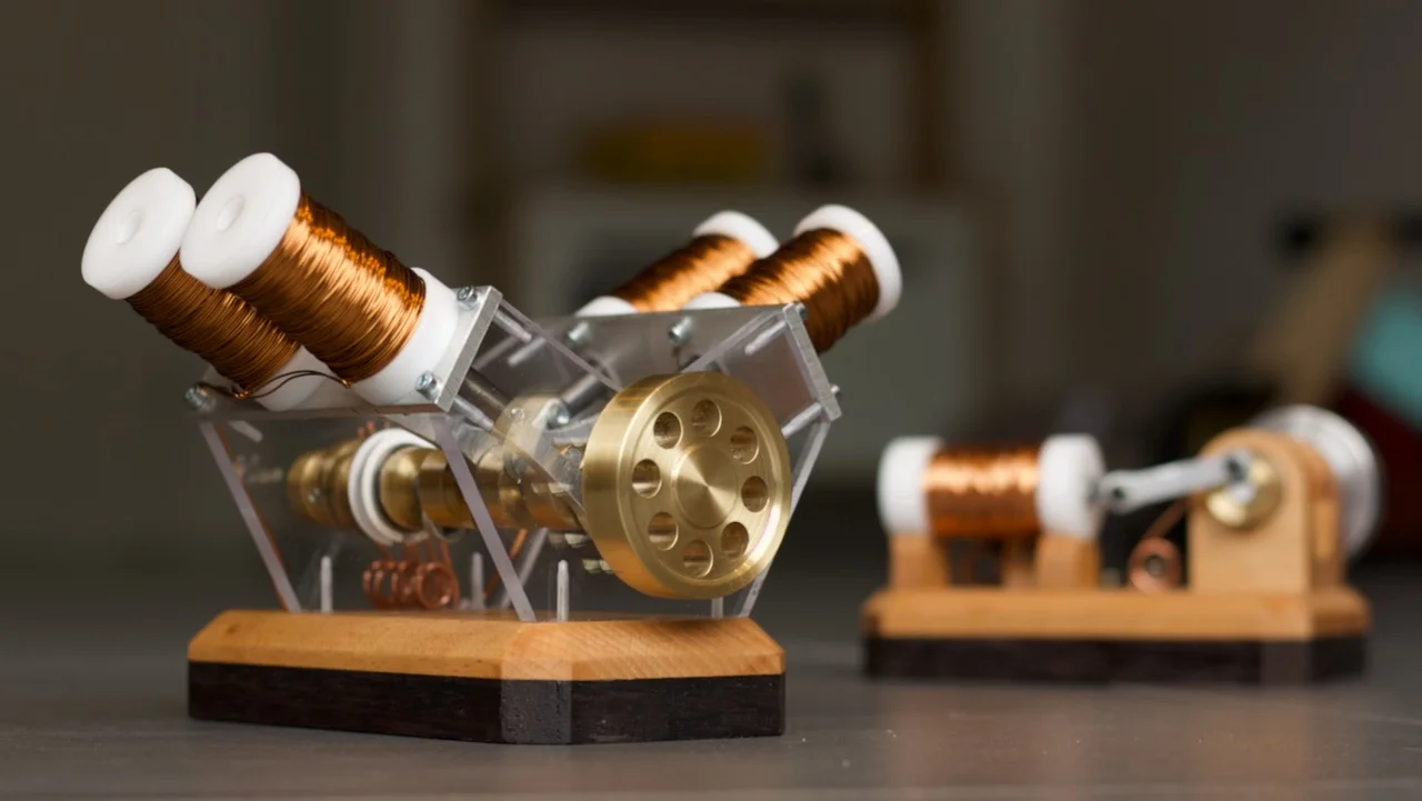
Where the one stroke version needs a kickstart by hand this four stroke instantly starts running as soon as it is powered. Having four ‘cilinders’ there is always one solenoid in the perfect position to pull. In theory this four stroke version should also go a bit quicker and have more torque. I cannot measure this but it actually doesn’t look too different from the first one on speed.
From the first version I learned that my switching mechanism is fiddly but it works well and I also got a feeling for the timing of the solenoid. I learned the hard way that any friction decreases its performance exponentially. With those things in mind I started the design for the new version.
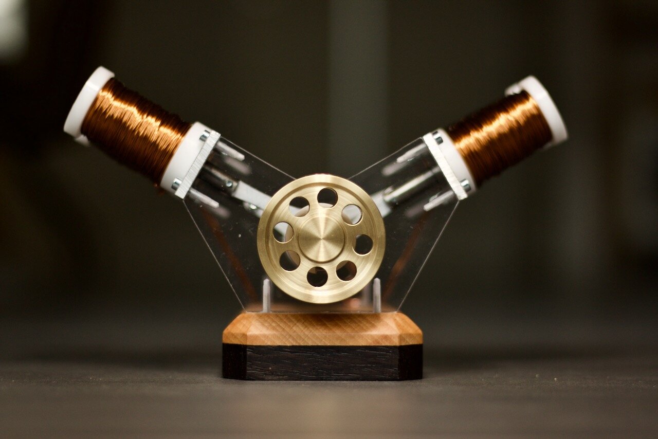
Four solenoids, but how? Having very little experience with combustion engines this is where I started my research. I wanted a V4 configuration and expected to be able to literally copy the timing as its done in a combustion engine. Turns out, I was wrong a four stroke engine turns two rounds to combust all four cilinders. Not what I want.
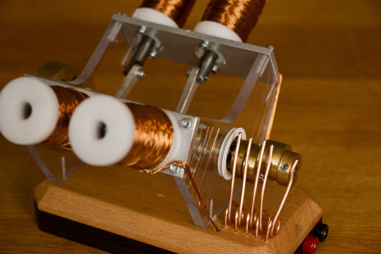
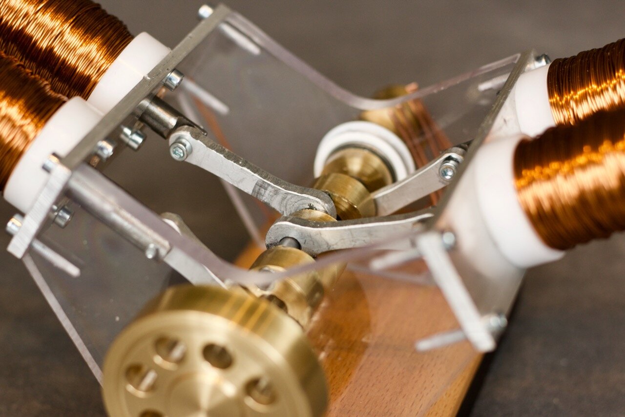
To space the cilinders so that exactly at every 90 degrees of the rotation one solenoid will fire would make for quite an interesting crankshaft so I decided to have opposing cilinders on the same spot at the crankshaft and see how that works out. (Spoiler alert: it works fine!)
Then my biggest struggle was the crankshaft. How am I going to put all these pieces together? In a YouTube video recently I saw someone using some loctite that works as a metal glue. A bit of research later and I found the number (Loctite 648) this stuff is intended to mimic a press fit when its not really a press fit. Perfect for this! I made all large pieces from 20mm round brass and the axles from 5mm steel rod. Gluing it in place and keeping the axle straight turned out a bit more challenging than expected and it ended up a bit curved. Luckily the rest of the assembly is not super rigid so this gives the thing some room to move.
I couldn’t let it happen that I spend all this work on this beauty of a crankshaft and not see it so I made the front and back of the solenoid engine of some nice 6 mm thick polycarbonate. This all combined with the large brass flywheel on the front makes it a beauty to look at.
Parts specs:
Power supply 12Volt 5 Amps
Mosfett type: FQP30N06L
Enamelled copper wire: 0,5 mm (estimated 50m per spool)
Spool resistance: 2 ohm