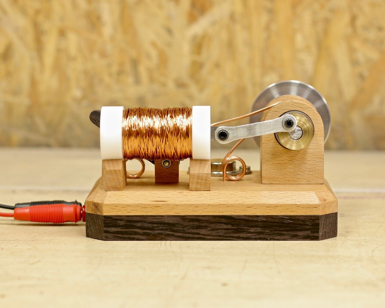
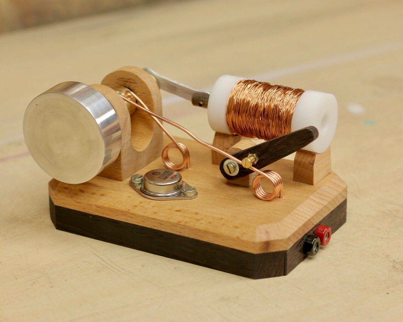
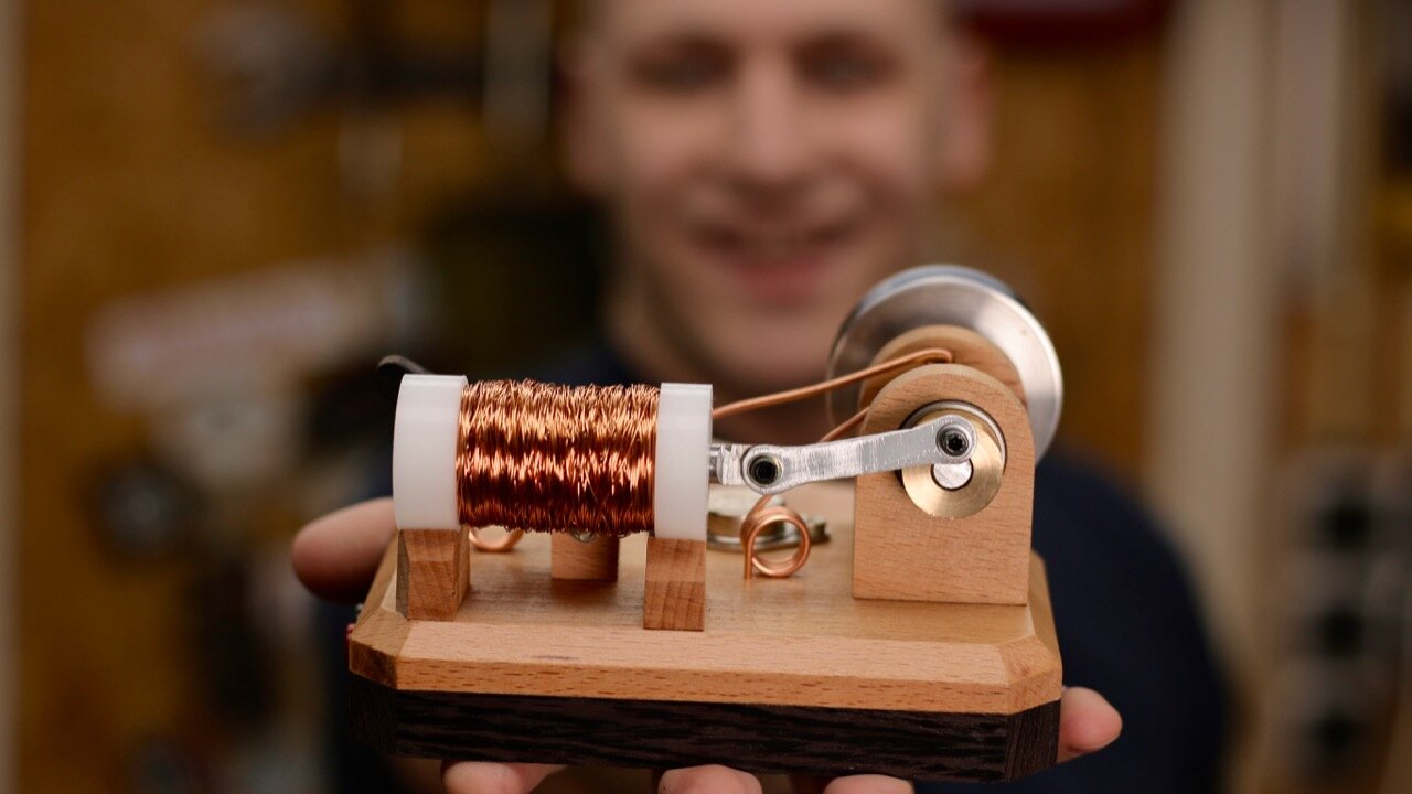
Solenoids are cool things. A solenoid is nothing more that a bunch of copper wire wrapped around a tube. But when you do that and you add some current it becomes an electromagnet. And those can be used for a lot of fun things.
I used solenoids in the past to control the flippers for the pinball machine and just recently I ran across a “How to make a solenoid engine” video and just had to make one.
A solenoid engine is a simplified version of a steam engine where the steam is replaced by the magnetism in the solenoid. By switching the solenoid on and off at the right time the plunger is pulled inside the coil resulting in one engine stroke. The mass of the flywheel then pulls the solenoid back to the far position ready to be pulled in again.
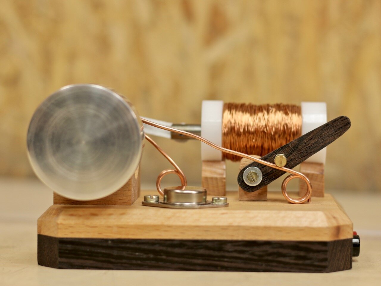
When researching online I found a lot of different ways to control the switching for the solenoid, ranging from fancy sensors to limit switches and sliding contacts. Being a big fan of visible mechanics and electronics I made a set of sliding contacts on an eccentric bushing. The idea here is that the sliding contact sometimes hits the bushing and sometimes not. This makes is possible to use it as a switch for the timing.
The cool thing about a solenoid engine is that there are endless options to make one. I went for wood combined with some metals, brass and aluminum, but it can also be 3d printed for example.
These are the components I used:
0,35 mm diameter enamelled copper wire (about 70 meter)
Transistor type number: 2N3055 *I chose this one for its looks but I have been told that a mosfett might be a better option
Flywheel: Aluminium
Bushings: Brass
